Matrices (tableaux d'éléments)
Dans le code on alloue de la mémoire pour une valeur, ensuite on l'initialise en lui donnant une valeur. On doit faire de même pour les matrices.
Si vous manipulez quelques minutes le logiciel Blender, vous pouvez perçevoir comment les objets sont tous composés d'une matrices, que ce soit pour la translation, la mise à l'échelle ou la rotation. Initialement ils sont créés avec les coordonnées 0, 0, 0. C'est l'espace de coordonnées qui est local à votre objet, là où il "démarre".
L'initialisation d'une matrice qui laisserait un vecteur complètement intacte lors de son utilisation (multiplication) : la matrice d'identité
\( \begin{bmatrix} 1 & 0 & 0 & 0 \\ 0 & 1 & 0 & 0 \\ 0 & 0 & 1 & 0 \\ 0 & 0 & 0 & 1 \end{bmatrix} \cdot \begin{bmatrix} 1 \\ 2 \\ 3 \\ 4 \end{bmatrix} = \begin{bmatrix} 1 \cdot 1 + 0 \cdot 2 + 0 \cdot 3 + 0 \cdot 4 \\ 0 \cdot 1 + 1 \cdot 2 + 0 \cdot 3 + 0 \cdot 4 \\ 0 \cdot 1 + 0 \cdot 2 + 1 \cdot 3 + 0 \cdot 4 \\ 0 \cdot 1 + 0 \cdot 2 + 0 \cdot 3 + 1 \cdot 4 \end{bmatrix} = \begin{bmatrix} 1 \\ 2 \\ 3 \\ 4 \end{bmatrix} \)
/// C++ — Exemple — update:18/05/26
simd::float4x4 identityMatrix()
{
    return (simd_float4x4) {
        (simd::float4) { 1.f, 0.f, 0.f, 0.f },
        (simd::float4) { 0.f, 1.f, 0.f, 0.f },
        (simd::float4) { 0.f, 0.f, 1.f, 0.f },
        (simd::float4) { 0.f, 0.f, 0.f, 1.f }};
}

// en pratique on utilisera matrix_identity_float4x4
simd::float4x4 identityMatrix = matrix_identity_float4x4;Local Space
Si cette même matrice local space a différentes valeurs, on l'appelera modelMatrix, on peut alors dire que la matrice ci-dessous correspond à la matrice world space de la caméra Blender dans Metal.
Model Matrix : float4x4
Les transformations principales
Scaling
\( \vec{x} = \begin{pmatrix} 3 \\ 2 \\ 0 \end{pmatrix} \)
Pour mettre à échelle le vecteur x le long de l’axe x de 0,5 — le rendant deux fois plus étroit, et mettre à échelle le vecteur x le long de l’axe y de 2 — le rendant deux fois plus haut. On décide qu’il devient le vecteur nommé y :
Comme je vous démontre cela par un cas 2D, gardez à l’esprit que Metal le considère comme étant dans un espace 3D. L’axe z sera réglé sur 1 afin de laisser le vecteur indemne.
\( \vec{x} \cdot \begin{pmatrix} 0.5 \\ 2 \\ 1 \end{pmatrix} = \begin{pmatrix} 3 \\ 2 \\ 0 \end{pmatrix} \cdot \begin{pmatrix} 0.5 \\ 2 \\ 1 \end{pmatrix} = \begin{pmatrix} 3 \cdot 0.5 \\ 2 \cdot 2 \\ 0 \cdot 1 \end{pmatrix} = \begin{pmatrix} 1.5 \\ 4 \\ 0 \end{pmatrix} \)
Ou avec la composante w qui servira par après et qui dont on a pas besoin pour une mise à l'échelle :
\( \begin{bmatrix} 3 & 0 & 0 & 0 \\ 0 & 2 & 0 & 0 \\ 0 & 0 & 0 & 0 \\ 0 & 0 & 0 & 1 \end{bmatrix} \cdot \begin{bmatrix} 0.5 & 0 & 0 & 0 \\ 0 & 2 & 0 & 0 \\ 0 & 0 & 1 & 0 \\ 0 & 0 & 0 & 1 \end{bmatrix} = \begin{bmatrix} 3 \cdot 0.5 \\ 2 \cdot 2 \\ 0 \cdot 1 \\ 1 \end{bmatrix} = \begin{bmatrix} 1.5 \\ 4 \\ 0 \\ 1 \end{bmatrix} \)
/* * * * * * * * * * * * * * * * * * * * * * * * * * * * * * */
/*                                        +       +          */
/*      File: Math.cpp            +++     +++                */
/*                                        +       +          */
/*      By: Laboitederemdal                +       +         */
/*                                       +           +       */
/*      Created: 19/09/2025 20:09:59      + + + + + +        */
/*      Updated: 18/05/2026                                  */
/* * * * * * * * * * * * * * * * * * * * * * * * * * * * * * */

#include "Math.hpp"

namespace math
{
simd::float4x4 makeScale(const simd::float3& s)
{
    return simd_matrix((simd::float4) { s.x, 0, 0, 0 },
                       (simd::float4) { 0, s.y, 0, 0 },
                       (simd::float4) { 0, 0, s.z, 0 },
                       (simd::float4) { 0, 0, 0, 1.0 });
}
Translation
Lors d’une translation, tu ajoutes un vecteur dit vecteur de traduction au-dessus du vecteur original, ce qui renvoie un nouveau vecteur avec une position différente.
Notation row-major pour représenter les mathématiques :
\( \begin{bmatrix} 3 & 0 & 0 & 0 \\ 0 & 2 & 0 & 0 \\ 0 & 0 & 0 & 0 \\ 0 & 0 & 0 & 1 \end{bmatrix} \cdot \begin{bmatrix} 1 & 0 & 0 & 0.5 \\ 0 & 1 & 0 & 2 \\ 0 & 0 & 1 & 1 \\ 0 & 0 & 0 & 1 \end{bmatrix} = \begin{bmatrix} 3 + 0.5 \cdot 1 \\ 2 + 2 \cdot 1 \\ 0 + 1 \cdot 1 \\ 1 \end{bmatrix} = \begin{bmatrix} 3.5 & 0 & 0 & 0 \\ 0 & 4 & 0 & 0 \\ 0 & 0 & 1 & 0 \\ 0 & 0 & 0 & 1 \end{bmatrix} \)
Le format natif de SIMD & Metal en notation est column-major (colonne par colonne). Les emplacements sur une matrice seraient les suivants :
/// C++ — Math.cpp — update:18/05/26
simd::float4x4 makeTranslate(const simd::float3& t)
{
    return simd_matrix((simd::float4) { 1.f, 0.f, 0.f, 0.f }, // column 0
                       (simd::float4) { 0.f, 1.f, 0.f, 0.f }, // column 1
                       (simd::float4) { 0.f, 0.f, 1.f, 0.f }, // column 2
                       (simd::float4) { t.x, t.y, t.z, 1.f }); // column 3 (1, 1, 2, 0.5)
}
Rotation
Une rotation en 2D ou 3D est représentée par un angle. J’utiliserai les unités de mesure degrés et/ou radians.
Rotation around the X-axis :
\( \begin{bmatrix} 1 & 0 & 0 & 0 \\ 0 & \cos\theta & \sin\theta & 0 \\ 0 & -\sin\theta & \cos\theta & 0 \\ 0 & 0 & 0 & 1 \end{bmatrix} \cdot \begin{bmatrix} x \\ y \\ z \\ 1 \end{bmatrix} = \begin{bmatrix} x \\ \cos\theta \cdot y + \sin\theta \cdot z \\ -\sin\theta \cdot y + \cos\theta \cdot z \\ 1 \end{bmatrix} \)
/// C++ — Math.cpp — update:18/05/26
simd::float4x4 makeXRotate(float angleRadians)
{
    const float a = angleRadians;
    return simd_matrix_from_rows((simd::float4) { 1.0f,     0.0f,    0.0f, 0.0f },
                                 (simd::float4) { 0.0f,  cosf(a), sinf(a), 0.0f },
                                 (simd::float4) { 0.0f, -sinf(a), cosf(a), 0.0f },
                                 (simd::float4) { 0.0f,     0.0f,    0.0f, 1.0f });
}

simd::float4x4 makeYRotate(float angleRadians)
{
    const float a = angleRadians;
    return simd_matrix_from_rows((simd::float4) {  cosf(a), 0.0f, sinf(a), 0.0f },
                                 (simd::float4) {     0.0f, 1.0f,    0.0f, 0.0f },
                                 (simd::float4) { -sinf(a), 0.0f, cosf(a), 0.0f },
                                 (simd::float4) {     0.0f, 0.0f,    0.0f, 1.0f });
}

simd::float4x4 makeZRotate(float angleRadians)
{
    const float a = angleRadians;
    return simd_matrix_from_rows((simd::float4) {  cosf(a), sinf(a), 0.0f, 0.0f },
                                 (simd::float4) { -sinf(a), cosf(a), 0.0f, 0.0f },
                                 (simd::float4) {     0.0f,    0.0f, 1.0f, 0.0f },
                                 (simd::float4) {     0.0f,    0.0f, 0.0f, 1.0f });
}
Pour effectuer plusieurs opérations d'un coup de vecteur de traduction, tu dois respecter ce sens :
Translation x Rotation x Scale — car S x T \( \textcolor{aqua}{\boldsymbol{≠}} \) T x S
T x S = \( \begin{bmatrix} 1 & 0 & 0 & 0.5 \\ 0 & 1 & 0 & 2 \\ 0 & 0 & 1 & 1 \\ 0 & 0 & 0 & 1 \end{bmatrix} \cdot \begin{bmatrix} 0.5 & 0 & 0 & 0 \\ 0 & 2 & 0 & 0 \\ 0 & 0 & 1 & 0 \\ 0 & 0 & 0 & 1 \end{bmatrix} = \begin{bmatrix} 0.5 & 0 & 0 & \textcolor{aqua}{\mathbf{0.5}} \\ 0 & 2 & 0 & \textcolor{aqua}{\mathbf{2}} \\ 0 & 0 & 1 & 1 \\ 0 & 0 & 0 & 1 \end{bmatrix} \)
S x T (mauvais) = \( \begin{bmatrix} 0.5 & 0 & 0 & 0 \\ 0 & 2 & 0 & 0 \\ 0 & 0 & 1 & 0 \\ 0 & 0 & 0 & 1 \end{bmatrix} \cdot \begin{bmatrix} 1 & 0 & 0 & 0.5 \\ 0 & 1 & 0 & 2 \\ 0 & 0 & 1 & 1 \\ 0 & 0 & 0 & 1 \end{bmatrix} = \begin{bmatrix} 0.5 & 0 & 0 & \textcolor{aqua}{\mathbf{0.25}} \\ 0 & 2 & 0 & \textcolor{aqua}{\mathbf{4}} \\ 0 & 0 & 1 & 1 \\ 0 & 0 & 0 & 1 \end{bmatrix} \)
\( \underbrace{\begin{bmatrix} 0.5 & 0 & 0 & 0.5 \\ 0 & 2 & 0 & -2 \\ 0 & 0 & 1 & 1 \\ 0 & 0 & 0 & 1 \end{bmatrix}}_{\text{T} \times \text{S}} \cdot \underbrace{\begin{bmatrix} 1 \\ 1 \\ 0 \\ 1 \end{bmatrix}}_{\text{vertex}} = \begin{bmatrix} 0.5 \cdot 1 + 0.5 \cdot 1 \\ 2 \cdot 1 + (-2) \cdot 1 \\ 0 + 1 \cdot 1 \\ 1 \end{bmatrix} = \underbrace{\begin{bmatrix} 1 \\ 4 \\ 1 \\ 1 \end{bmatrix}}_{\text{résultat}} \)
Le pipeline de transformation
/// .metal — pipeline de transformation classique
// Le vertex shader reçoit un float3 (position objet)
// et le projette en espace clip via trois matrices.

// Côté CPU — construction des matrices (simd)
simd::float4x4 model      = makeTranslation(pos) * makeRotationY(angle);
simd::float4x4 view       = makeLookAt(eye, center, up);
simd::float4x4 projection = makePerspective(fovY, aspect, near, far);
simd::float4x4 mvp        = projection * view * model;

// Côté GPU — application au vecteur
vertex float4 vert_main(float3 position [[attribute(0)]],
                        constant Uniforms& u [[buffer(0)]])
{
    // float3 → float4 : w=1 pour les points, w=0 pour les directions
    float4 worldPos = u.mvp * float4(position, 1.0);
    return worldPos;
}

// Transformer une normale : on utilise l'inverse-transposée de la model matrix
// (évite la déformation si la scale n'est pas uniforme)
float3 worldNormal = normalize((u.normalMatrix * float4(normal, 0.0)).xyz);
// Dans le vertex shader, chaque vertex passe par 3 transformations :
float4 worldPos = uniforms.modelMatrix * float4(in.position, 1.0);
// ↑ local → world : applique position/rotation/scale de l'objet
float4 viewPos = uniforms.viewMatrix * worldPos;
// ↑ world → view : ramène la caméra à l'origine
float4 clipPos = uniforms.projMatrix * viewPos;
// ↑ view → clip : applique la perspective (les objets lointains rapetissent)
out.position = clipPos; // le GPU fait ensuite la division par w → NDC — Screen SpaceChaque vertex passe par cette chaîne — de gauche à droite, chaque matrice change l'espace :
\[ \mathbf{v}_{clip} = \underbrace{P}_{\text{proj}} \times \underbrace{V}_{\text{view}} \times \underbrace{M}_{\text{model}} \times \underbrace{\mathbf{v}_{local}}_{\text{vertex}} \]
① Model Matrix — Local → World
\( M = T \times R \times S \) — position, rotation, scale de l'objet dans le monde
Une matrice peut s'écrire avec des paranthèses, afin de bien distinguer les opérations, j'utilise les crochets qui est plus fréquent :
Matrice 4 x Matrice 4 = Matrice 4
Matrice 4 x Vecteur 4 = Vecteur 4
\[ \mathbf{v}_{world} = M \cdot \mathbf{v}_{local} = \begin{bmatrix} r_{00}s_x & r_{01}s_y & r_{02}s_z & t_x \\ r_{10}s_x & r_{11}s_y & r_{12}s_z & t_y \\ r_{20}s_x & r_{21}s_y & r_{22}s_z & t_z \\ 0 & 0 & 0 & 1 \end{bmatrix} \cdot \begin{pmatrix} x \\ y \\ z \\ 1 \end{pmatrix} = \begin{pmatrix} x' \\ y' \\ z' \\ 1 \end{pmatrix} \]
World Space
② View Matrix — World → View
La caméra est ramenée à l'origine. \( V = M_{camera}^{-1} \) — inverse de la world matrix de la caméra.
\[ \mathbf{v}_{view} = V \cdot \mathbf{v}_{world} = \begin{bmatrix} r_x & r_y & r_z & -\mathbf{r}\cdot\mathbf{pos} \\ u_x & u_y & u_z & -\mathbf{u}\cdot\mathbf{pos} \\ f_x & f_y & f_z & -\mathbf{f}\cdot\mathbf{pos} \\ 0 & 0 & 0 & 1 \end{bmatrix} \cdot \begin{pmatrix} x' \\ y' \\ z' \\ 1 \end{pmatrix} \]
où \(\mathbf{r}\) = right, \(\mathbf{u}\) = up, \(\mathbf{f}\) = forward de la caméra.
View Space
③ Projection Matrix — View → Clip
La perspective : les objets lointains rapetissent. \( f = \frac{1}{\tan(\text{fov}/2)} \)
\[ P = \begin{bmatrix} \dfrac{f}{\text{aspect}} & 0 & 0 & 0 \\[10pt] 0 & f & 0 & 0 \\[10pt] 0 & 0 & \dfrac{\text{far}}{\text{near}-\text{far}} & \dfrac{\text{near} \cdot \text{far}}{\text{near}-\text{far}} \\[10pt] 0 & 0 & -1 & 0 \end{bmatrix} \]
/// C++ — Math.cpp — update:18/05/26
simd::float4x4 makePerspective(float fovRadians, float aspect, float znear, float zfar)
{
    float f  = 1.f / tanf(fovRadians * 0.5f); // cotangente du demi-FOV — scale vertical
    float zs = zfar / (zfar - znear); // remapping Z → [0, 1] (Metal NDC)
    return simd::float4x4((simd::float4){ f / aspect, 0,  0,          0 },
                          (simd::float4){ 0,          f,  0,          0 },
                          (simd::float4){ 0,          0,  zs,         1 },
                          (simd::float4){ 0,          0, -znear * zs, 0 });
} // f / aspect = va_tan / aspect → scale horizontal
\[ \mathbf{v}_{clip} = P \cdot \mathbf{v}_{view} = \begin{pmatrix} x_{clip} \\ y_{clip} \\ z_{clip} \\ w_{clip} \end{pmatrix} \quad \text{où} \quad w_{clip} = -z_{view} \quad \text (perspective \quad \text divide) \]
Clip Space
④ Division par w — Clip → NDC
Le GPU effectue cette étape automatiquement (perspective divide) :
\[ \mathbf{v}_{NDC} = \frac{\mathbf{v}_{clip}}{w_{clip}} = \begin{pmatrix} x_{clip}/w \\ y_{clip}/w \\ z_{clip}/w \\ 1 \end{pmatrix} \in [-1, 1]^3 \]
Plus \( z_{view} \) est grand (objet loin), plus \( w_{clip} \) est grand, plus \( x/w \) et \( y/w \) sont petits — l'objet rapetisse. C'est toute la magie de la perspective.
En Metal après cette division : \( z_{NDC} \in [0, 1] \) (pas \([-1,1]\) comme OpenGL) — \(0\) = near, \(1\) = far.
Différentes projections
Vue Orthographique dans le logiciel Blender avec coordonnées de la position de la caméra.
Remarque : notre caméra sera placée sur un des axes (X ici, Z avec Metal) et regardera aussi au centre.
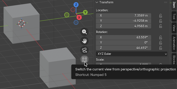
Remarque : le centre du cube est au croisement des 3 axes de la matrice d'identité du cube, comme dans notre code, tu peux placer ta caméra de la même manière malgré les axes différemment nommé.
/// C++ — Math.cpp — update:18/05/26
simd::float4x4 makeOrthographic(float left, float right, float top, float back, float near, float far) // back/bottom
{
    return simd::float4x4((simd::float4){           2.f / (right-left),                        0,                  0, 0 },
                          (simd::float4){                            0,         2.f / (top-back),                  0, 0 },
                          (simd::float4){                            0,                        0,   1.f / (far-near), 0 },
                          (simd::float4){ -(right+left) / (right-left), -(top+back) / (top-back), -near / (far-near), 1 });
}
} // namespace MathTout le polygon 3D (ligne continue) s'appelle la View Fructum.
Les 6 faces des polygones s'appellent frustumPlanes.
Nos matrices stockées de manière structurée
La structure CameraUniforms est partagée entre C++ et MSL via render_shared.h. Elle contient toutes les matrices nécessaires, précalculées une seule fois par frame côté CPU.
Structure de cette manière pour la cohérence des chapitres suivants :
/// C++ — Renderer_shared.h — update:18/05/26
struct alignas(16) CameraUniforms
{   // Local Space → World Space aka modelMatrix est propre à chaques shaders (généralement buffer(1))
    simd::float4x4 viewMatrix;                     // World Space → View Space
    simd::float4x4 projectionMatrix;               // View Space  → Clip Space
    simd::float4x4 viewProjectionMatrix;           // World Space → Clip Space (P × V combiné)
    simd::float4x4 invViewProjectionMatrix;        // Clip Space  → World Space (Pour la skybox, raycast)
    simd::float4x4 invProjectionMatrix;            // Clip Space  → View Space (deferred lighting)
    simd::float4x4 invViewMatrix;                  // View Space  → World Space
    simd::float4x4 invOrientationProjectionMatrix; // Clip Space  → World Space (SANS translation, P × R seulement)
};

struct alignas(16) GlobalUniforms
{
    CameraUniforms cameraUniforms;
};
alignas(16) garantit ça côté C++. Sur Apple Silicon (mémoire unifiée), cette même structure est lue directement par le GPU sans copie.
Si tu veux imprimer la taille de cette "grosse" structure côté C++, place ceci dans le constructeur du rendu principal :
/// C++ — Renderer.cpp — update:18/05/26
{
    printf("sizeof CameraUniforms %lu\n", sizeof(CameraUniforms));
}
float4x4 = 4 * 16 = 64 et CameraUniforms = 64 * 7 matrices = 448 bytes
/// C++ — Math.hpp — update:18/05/26
#ifndef Math_hpp
#define Math_hpp

#include <simd/simd.h>

namespace math
{
    simd::float4x4 makeOrthographic(float left, float right, float top, float bottom, float near, float far);
    simd::float4x4 makePerspective(float fovRadians, float aspect, float znear, float zfar);
    simd::float4x4 makeXRotate(float angleRadians);
    simd::float4x4 makeYRotate(float angleRadians);
    simd::float4x4 makeZRotate(float angleRadians);
    simd::float4x4 makeTranslate(const simd::float3& v);
    simd::float4x4 makeScale(const simd::float3& v);
}

#endif /* Math_hpp */
Quaternions — rotations sans gimbal lock
Les quaternions sont la façon correcte de représenter les rotations 3D — pas de gimbal lock, interpolation fluide (SLERP).
// simd côté CPU :
simd_quatf q = simd_quaternion(angle, axis); // rotation d'angle autour d'axis
simd::float4x4 m = simd_matrix4x4(q);        // → matrice pour le shader

// SLERP — interpolation sphérique entre deux rotations
simd_quatf result = simd_slerp(q1, q2, t);